Understanding Types of Tolerance in Engineering: A Comprehensive Guide
Date:2026-05-22
View: 2738 Point
Engineering tolerance is the core standard that connects design theory and physical manufacturing, and stipulates the permissible deviation range of component size, shape and surface. Reasonable tolerance setting can not only guarantee the assembly suitability and operational stability of parts, but also balance the production accuracy and manufacturing costs, which is the basic guarantee for high quality production of aluminum profiles, precision machinery and other industries.
What Is Tolerance in Engineering
Tolerance in Engineering refers to the maximum allowable range of variation in the physical dimensions of a part, and is the core basis for controlling product accuracy in the manufacturing industry. All mechanical parts cannot be produced to an absolute standard size, and tolerance is the standardized threshold set for such reasonable production deviations. Tolerance value is usually in millimeters or inches as a unit, the core role is to protect the interchangeability of parts and the use of function. Adaptive components such as bearings and precision aluminum profiles rely on precise tolerances to control small dimensional deviations and avoid assembly failures. At the same time, the tolerance design will take into account the whole life cycle loss of the product, leaving a reasonable deviation space to offset the wear and deformation of the parts generated by long-term use. The industry's commonly used maximum solid state tolerance standard can maximize the adaptation of production deviations under the premise of guaranteeing structural integrity. Tolerance zones in engineering drawings are not set arbitrarily, but are calculated by combining the function of the part, the production process, and the precision of the equipment. For example, conventional tolerance intervals for CNC machining of steel parts and aluminum profiles not only fit the machining capability of the equipment, but also meet the product usage standards.
Why Tolerances Matter
Guaranteeing the Universality of Parts Adaptation
Standardized tolerances can unify the accuracy standards for parts production, so that parts processed by different equipment and batches can be matched and assembled, and parts can be freely exchanged. This feature greatly simplifies the assembly process of industrialized mass production, effectively shortens the assembly and processing time, and comprehensively meets the production requirements of large-scale mass production.
Determine Product Performance and Safety of Use
Tolerance directly determines the alignment accuracy of the mechanical system, and at the same time affects the friction coefficient and overall stress distribution of the equipment operation. It is the core parameter to control the running status of mechanical products. Precision aluminum profiles, aerospace parts and other high-end products rely on accurate tolerance control of deformation deviation. It can effectively improve the durability and stability of the product, and avoid various types of safety hazards.
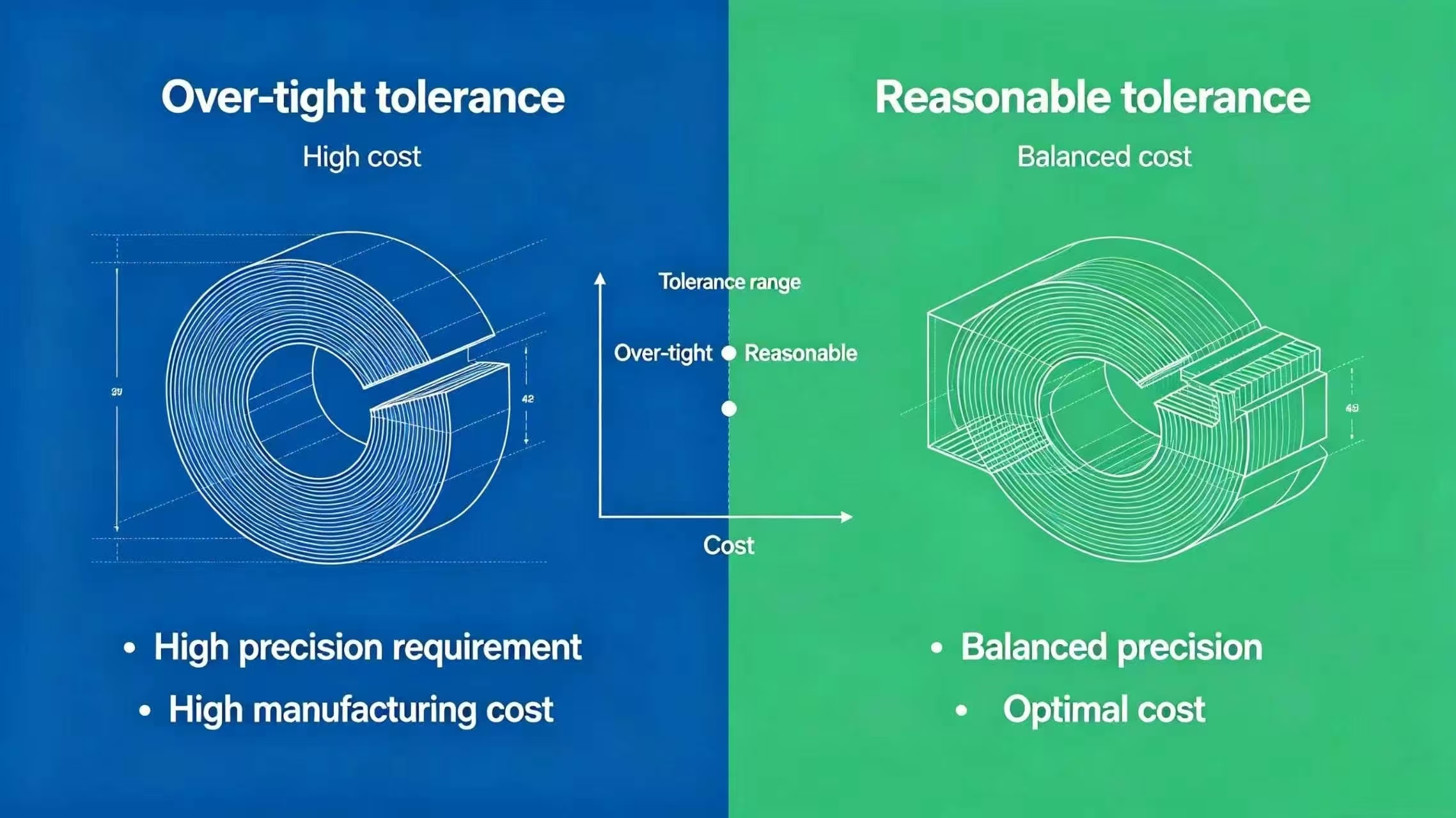
Balancing Production Accuracy and Manufacturing Cost
Setting the tolerance standard too tightly will significantly increase the difficulty of parts processing, and put forward extremely high requirements for processing equipment and process precision. This will directly increase the grinding process, increase the scrap rate, and significantly increase the overall production and quality control costs. Scientific and reasonable tolerance settings, can guarantee the use of product performance on the basis of effective simplification of the processing production process. Not only can avoid unnecessary process losses, but also accurately control production costs, to maximize the cost-effective.
Avoid Product Failure and After-sales Recall Risk
Unreasonable tolerance control can easily cause parts misalignment, excessive wear, equipment jamming and other failure problems. In serious cases, this can lead to batch failure and affect the production and delivery schedule. Scientific and standardized tolerance design and whole process control can avoid the hidden danger of parts operation from the source. Effectively reduce the probability of product failure, help companies to reduce after-sales costs and maintain brand reputation.
Main Types of Tolerances in Engineering
Dimensional Tolerances
Dimensional tolerances are the most basic types of tolerances in engineering, mainly controlling the deviation of physical dimensions such as length, diameter, wall thickness, slot width, etc., which are widely used in all kinds of machinery and aluminum parts processing. There are obvious differences in the dimensional tolerance standards for different functional parts. Non-load-bearing common brackets are commonly used with ±0.1mm tolerance, CNC precision positioning surfaces are used with ±0.05mm tolerance, and high-precision scenarios such as bearing fits need to be strictly controlled with ±0.01mm deviation. The higher the tolerance precision, the more complex the processing procedures, and the risk of scrap is also increased. Therefore, the industry generally follows the principle of control on demand, tightening tolerances on key parts such as bushings, bearing housings, aluminum precision assembly bits, and relaxing standards on non-functional surfaces. Taking 10.00mm nominal diameter shaft parts as an example, ±0.05mm dimensional tolerance corresponds to a qualified size range of 9.95mm to 10.05mm, which can guarantee the precise transition fit and interference fit with the supporting holes.
Geometric Tolerance
Geometric tolerance is used to control the shape, spatial position and angular relationship of parts, to make up for the shortcomings of dimensional tolerance that can not constrain the shape and orientation deviation of parts, and is the core standard of complex precision assembly. Geometric tolerances are divided into four main categories, namely, shape tolerances for controlling part form, directional tolerances for controlling angular orientation, positional tolerances for controlling positional deviation, and runout tolerances for controlling rotating parts. Maximum and minimum solid state standards are commonly used in the industry to match the extreme production state of a part. Positional tolerances for aluminum profiles and shaft parts can be used to guarantee assembly accuracy while relaxing reasonable production deviations and improving machining tolerance. The standardized geometric tolerance specification unifies the technical standards of design and production, reduces cross-departmental communication deviation, and makes the processing and quality inspection of complex structural parts more standardized and efficient.
Surface Roughness Tolerance
Surface roughness tolerance controls the allowable deviation of the surface texture of parts, commonly used Ra, Rz numerical labeling, directly affecting the parts wear resistance, sealing, friction and the appearance of texture. CNC machining scenarios have mature roughness standards, ordinary milling surface Ra value of 3.2 μm, general-purpose precision parts control in 1.6 μm, sealing surfaces, sliding contact surfaces need to reach 0.8 μm, optical precision parts need to be less than 0.4 μm. Aluminum anodizing, polishing, sandblasting and other post-treatment processes will change the original surface roughness. It is necessary to reserve space for deviation in advance at the design stage, so as to avoid substandard surface accuracy caused by post-treatment.
Shape Tolerance
According to DIN EN ISO 1101 standard, shape tolerance contains six core indexes, specializing in controlling the form deviation of a single component element without reference to other benchmarks, which is the guarantee of basic form and position accuracy. Straightness controls the straightness deviation of lines and shafts. The 0.05mm straightness tolerance requires that the measured line is within the corresponding tolerance interval throughout the entire length of the line, which is commonly used for controlling the deformation of long aluminum profiles and shaft parts. Flatness is the most widely used shape tolerance, focusing on controlling the flatness of sealing surface and assembly surface, and the flatness tolerance of precision sealing area is usually controlled between 0.01mm and 0.05mm. In addition, roundness, cylindricity, line contour, surface contour also belongs to the shape tolerance, mostly used in bearing housings, circular pipe fittings and other parts, strict control of the cross-section and the overall form of the deviation, to avoid abnormal wear and tear.
Positional Tolerance
Positional tolerance takes the reference element as a reference to control the positional and angular deviation of the parts' features, which is mainly divided into three categories of directional tolerance, positional tolerance and runout tolerance, and is the key to precision assembly. Direction tolerance includes parallelism, perpendicularity and angularity, and 0.03mm parallelism tolerance can ensure that the fitting surface of the part is accurately parallel to the datum surface, which is widely used in aluminum frame and shaft hole assembly scenarios. Position tolerance controls the offset deviation of hole position, axis and symmetry surface to ensure that the key structure of the parts is in the theoretical precise position, which is the core basis for the processing of porous aluminum profile panel and precision bracket. Runout tolerance applies to shafts and rotating parts, and the circular runout tolerance of precision shafts is usually controlled at 0.01mm to 0.03mm, which can effectively avoid vibration and eccentricity problems during the operation of equipment.
Standard Tolerance Systems and Specifications
ISO 2768 International Standard
ISO 2768 is a global standard for machining tolerances for linear and angular dimensions without special markings, suitable for most industrial scenarios such as CNC machining and aluminum extrusion. The standard classifies machining accuracy into four grades: fine, medium, rough and ultra rough, and also divides geometric tolerance grades H, K and L, which can be adapted to the needs of production with different accuracy and different cost as required. The drawing labeling ISO 2768-mK represents the implementation of medium precision standards for linear dimensions and K-level precision for geometric features, which eliminates the need to label dimensional tolerances one by one and simplifies the drawing design process. ISO 2768 is a general basic standard, but for special high-precision scenarios such as aerospace, medical, precision electronics, etc., it is necessary to mark tightening tolerances separately, replacing the general standard to ensure that the product accuracy meets the standard.
Tolerance System
Overview of Fit Tolerance
Fitting tolerance is the core standard for controlling the tightness of paired parts assembly, and is an important foundation for mechanical assembly design. The industry mainly categorizes them into three types, which are suitable for different equipment assembly and working conditions. Reasonable selection of the type of fit can accurately control the assembly status of the parts, taking into account the stability of the structure and practicality of disassembly, to meet the needs of various types of machinery production.
Clearance Fit
The size of the shaft body of the clearance fit is always smaller than the corresponding hole size, and a small uniform gap will be left after assembly. This structural feature ensures flexible sliding and rotating of the parts with less running resistance. Clearance fits are widely used in general transmission structures and movable joints, and are one of the most commonly used forms of fit in the dynamic assembly of machinery.
Interference Fit
The size of the shaft parts with interference fit is slightly larger than the hole size, and the parts fit tightly without any gap after assembly. Relying on the size of the extrusion to achieve self-locking fixed, without the need for screws, glue and other auxiliary fixed accessories. This type of fit is rigid, anti-torque performance is excellent, mostly used in the need for long-term fixation, do not allow loose displacement of the precision connection structure.
Transition Fit
Transitional fits are characterized by the presence of cross-section deviations in the dimensions of the parts and uncertainty in the assembly effect. After assembly, there may be a small gap or a slight overfilling state. This type of fit combines ease of assembly and positioning accuracy with higher fault tolerance, and is generally applicable to all types of precision positioning assembly scenarios.
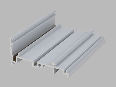
Tolerance in Aluminum Profile Manufacturing
Aluminum profiles are lightweight, easily deformed, and prone to deviation during processing, extrusion, and post-processing. Tolerances of various types need to be controlled to ensure profile assembly accuracy and structural stability.
Surface Flatness Control
The flatness directly affects the sealing effect and assembly fit of aluminum profiles. For conventional CNC machining of aluminum profiles, the flatness deviation within each 100mm length should be controlled between 0.05mm and 0.3mm. Thin-walled, large-span aluminum profiles are prone to deformation, warping problems, the production of stress relief processing, vacuum clamping and other processes, strict control of flatness deviation, to protect the overall flatness.
Straightness Control of Long Profiles
Long extruded aluminum profiles are susceptible to bending and deformation due to residual stress, and the industry's conventional standard is that the straightness deviation should not be more than 0.1mm to 0.3mm for every 300mm length. Different aluminum alloy materials have different stability, T6 tempered aluminum has stronger dimensional stability and smaller straightness deviation, which is more suitable for the production of high-precision long profile structural parts.
Hole Position Control
The positional accuracy of the mechanically connected holes of aluminum profiles is crucial. Relying on stable datum positioning, the positional deviation of conventional holes can be controlled from ±0.05mm to ±0.10mm. The hole position deviation of large-size aluminum profile panels is easy to accumulate, and mass production needs to be detected with three-coordinate measuring equipment to avoid assembly misalignment problems caused by the superposition of errors.
Wall Thickness Precision Control
Aluminum thin-wall structure processing is prone to vibration, chipping, deformation problems, milling processing of stable minimum wall thickness should be maintained at 0.8mm to 1.0mm. Ultra-high and ultra-thin aluminum profile structure is easy to bend and deform, through the addition of reinforcing bars, optimize the processing technology to stabilize the wall thickness size, to ensure that the tolerance is up to standard.
Thread Precision Control
Aluminum profile threads directly processed by CNC can reach 6H/2B accuracy level stably to meet the demand of regular connection. Threaded parts with high load and high frequency use need to be equipped with thread sheaths to improve durability. Thread tolerance focuses on the control of the center diameter and positional deviation, to avoid thread offset and poor occlusion, and to protect the connection strength and disassembly stability of aluminum components.
How to Choose the Right Tolerance
Define the Core Accuracy Requirements
Before carrying out the tolerance design work, it is necessary to comprehensively sort out the actual function of the parts. Accurately distinguish between critical assembly parts and common appearance parts to provide a basis for tolerance setting. For core structures such as movable connections, sealing and fitting, and precise positioning, the tolerance standard needs to be tightened. For non-functional areas that are purely cosmetic and not subject to force, the tolerance requirements can be appropriately relaxed to reduce production difficulties.
Balance Precision and Cost
Tolerance accuracy is positively correlated with production cost and processing difficulty, the higher the accuracy requirements, the more complex the production process. Tight tolerance standards will significantly increase the parts scrap rate, resulting in unnecessary production losses. Designers should not blindly tighten the tolerance parameters, the actual use of the product function as the core bottom line. Weigh the relationship between precision and cost scientifically, and set reasonable tolerance ranges that take into account quality and cost-effectiveness.
Adaptation With Material Properties
The physical properties of different raw materials vary, with different degrees of thermal expansion and contraction and deformation. Aluminum profiles and plastic parts are more sensitive to changes in temperature and humidity, and are prone to dimensional deviations during processing and use. In the tolerance design stage, it is necessary to reserve an exclusive margin in combination with the material characteristics. By reserving space for deformation scientifically, the dimensional errors caused by environmental changes can be effectively offset, and the accuracy of the parts can be guaranteed to be stable.
Matching Production Equipment Capacity
There is an obvious gap between the upper limit of precision of various types of processing equipment, and the precision of CNC machining is higher, far exceeding that of traditional processes such as welding and casting. The machining error ranges of different equipment are different, and there is a fixed boundary of process accuracy. Design tolerances must be adapted to the processing capability of the existing equipment, is strictly prohibited to set the upper limit of precision beyond the equipment of the harsh parameters. This ensures that the production can be realized, effectively reducing the probability of processing scrap and rework.
Taking Into account the Entire Production Process
Parts plating, spraying, anodizing and other post-treatment processes will form a thin layer structure on the surface of the profile. The accumulation of such layers will directly change the original molding dimensions of the part, resulting in minor deviations. Tolerances must be set aside at the design stage to offset the incremental dimensions brought about by the coating. This can effectively avoid the problem of over-dimensioning of parts after post-processing, and ensure that the assembly precision of the finished product meets the standard.
Avoidance of Accumulated Tolerance Deviation
In the process of assembling multiple parts, the small tolerance errors of individual parts will be accumulated continuously. The accumulation of errors to a certain extent will affect the assembly accuracy of the overall structure. Strict control of the tolerance parameters of each component is required at the design and production stages. Effectively weaken the effect of error superposition, from the root to avoid the overall assembly misalignment, assembly failure and other problems.
Integration and Optimization of Tolerance Scheme
The design of the tolerance program needs to take into account the function of the product, material characteristics, processing equipment and production technology. Integrate the core influencing factors to build a scientific and complete tolerance design system. The finalized tolerance parameters need to be clearly marked in the design drawings, and at the same time, comprehensively check the error superposition, datum conflict and other potential problems. Avoid production hazards from the source, and ensure the accuracy of parts processing and assembly.
Common Engineering Tolerance Mistakes
Blindly Tighten Tolerance Standards
In order to avoid risks, many designers tighten the tolerances of all parts indiscriminately. Although it can guarantee the accuracy, it will greatly increase the processing time, equipment loss and scrap rate, resulting in unnecessary cost waste. A reasonable way to optimize is to accurately distinguish between critical parts and common parts, tighten tolerances only for core functional surfaces, and use common standards for the rest of the parts, taking into account both accuracy and cost-effectiveness.
Over-reliance on Drawing Default Tolerances
The generalized default tolerances in the title bar of the drawing are only applicable to general scenarios and cannot be adapted to all special structures. Complete reliance on the default standard may lead to the problem of insufficient precision in critical parts and excessive precision in common parts. It is necessary to mark the tolerance separately for special functional structures, and update the default standard of drawings regularly to fit the actual production capacity of the factory and reduce the ambiguity of production.
Unreasonable Selection of Datum
The datum is the core reference for tolerance inspection. Improper selection of datum will lead to inconsistency in processing and inspection standards, which will lead to misalignment of parts, rework and scrapping, etc. It is a common core misunderstanding in tolerance control. Benchmarks need to be adapted to the contact surface of the part assembly, clarify the primary and secondary benchmarks, and deduce the superimposed effect of the assembly tolerance in advance to ensure that the benchmark program is suitable for the actual assembly scenario.
Neglecting Positional Tolerance Control
Labeling only dimensional tolerances, omitting positional tolerances, will lead to holes, structural orientation without precise control standards, drawing interpretation ambiguity, easy to assemble misalignment after processing, poor fit. For parts with multiple holes and symmetrical structures, GD&T positional tolerance marking, combined with datum and tolerance correction symbols, should be used to clarify the precise machining and inspection standards.
Ignore the Difference of Process Deviation
The deviation ranges of different production processes vary greatly, and the upper accuracy limits of CNC machining, injection molding, and sheet metal forming are different, so uniformly applying the same tolerance standard will result in some processes failing to meet the standard. It is necessary to set the tolerance according to the classification of the processing process, and label the process adaptation requirements, so that the tolerance standard can be adapted to the actual production capacity, and the product qualification rate can be improved.
Excessive Control of Non-functional Surfaces
Tightening the tolerance for surfaces that are not assembled, not subjected to force, and only for appearance will greatly increase the workload of processing and quality control, but cannot improve product performance, which is ineffective precision control. Non-functional surfaces can be relaxed to general tolerance standards, and appearance parts are only targeted to control appearance defects, without excessive constraints on size and form deviation.
Supplier Technical Documents Are Not Clear
Fuzzy labeling of drawings, missing testing standards, and non-standardized use of symbols can lead to deviations in interpretation by suppliers, and the production of products that do not conform to the design requirements, which can lead to rework and delay problems. It is necessary to unify the specification of drawing labeling, clarify the testing equipment and sampling standards, and keep the record of version change to ensure the uniformity of the tolerance standards of both supply and demand sides.
Future Trends, A New Era of Tolerance in the Digital and Intelligent Age
Shift from 2D Drawing Tolerance to 3D Model Definition
Traditional two-dimensional drawing tolerance labeling is prone to interpretation bias, the industry is gradually popularizing three-dimensional model definition technology, tolerance, geometric parameters, production information directly integrated into the 3D model. This model opens up the whole process of design, production and inspection data, eliminates information bias, builds a digital production chain, and significantly improves the accuracy and consistency of tolerance control.
Digital Twin Closed-loop Tolerance Control
Relying on digital twin technology, we can build a virtual model of the part, real-time docking production line inspection data, and dynamically track the size deviation of the part and process fluctuations. Through real-time data feedback, engineers can predict the deviation trend in advance, actively adjust production parameters, and change the tolerance control from rectification to prevention and optimization. Intelligent adaptive production equipment can adjust the machining trajectory in real time according to the small deviation of the parts, realizing adaptive correction of deviation, and significantly improving the qualification rate of precision parts.
Artificial intelligence technology can deeply analyze massive production data, sort out the correlation laws between equipment status, environment, material and tolerance deviation, and accurately predict hidden quality problems. The AI intelligent system can synthesize the functional requirements, production costs, and process capabilities to automatically optimize the tolerance allocation scheme, replacing the traditional manual judgment to achieve the global optimal control. In the future, the tolerance control will enter the stage of dataization and intelligence, and upgrade from fixed standard control to dynamic adaptive control to meet the development needs of high-end precision manufacturing.
Conclusion
Engineering tolerance is the core system of precision control in manufacturing industry, covering multiple dimensions such as size, geometry, surface roughness, etc. It runs through the whole production process of aluminum profiles and various parts. Reasonable selection of tolerance standards, avoiding common misconceptions, and adapting the production process can effectively balance product precision, performance and cost. With the upgrading of digital technology, intelligent tolerance control will promote the manufacturing industry to high-precision, high-efficiency, low-cost direction of continuous iteration.
Henan Retop Industrial Co., Ltd. Will Be There Whenever Wherever Whatever You Need
 Balancing Production Accuracy and Manufacturing Cost
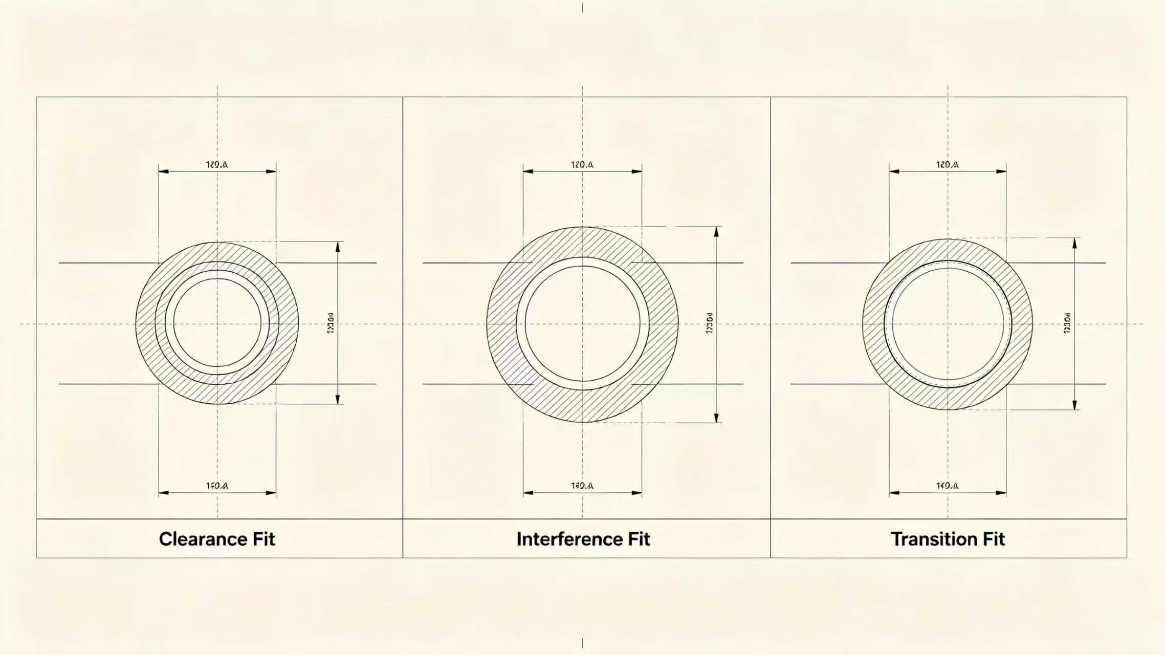 Tolerance System
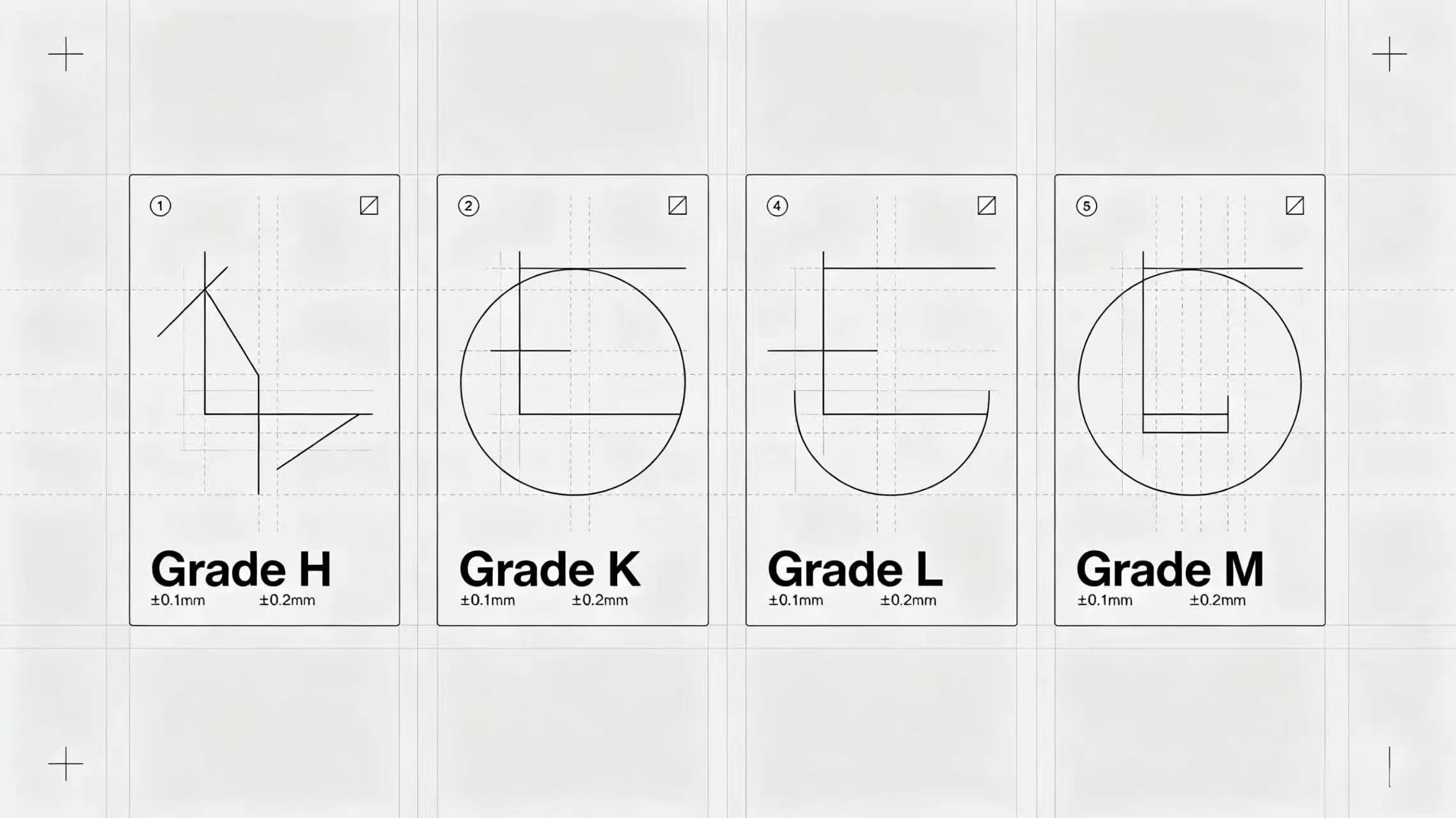 How to Choose the Right Tolerance
 Artificial Intelligence Driven Intelligent Tolerance Allocation